
Building an agricultural biogas plant: components and the flow of material step by step
From the silage clamp to the digestate tank: an overview of all the elements of a typical agricultural biogas plant, their functions and the dependencies between them.
Other language versions: polski.
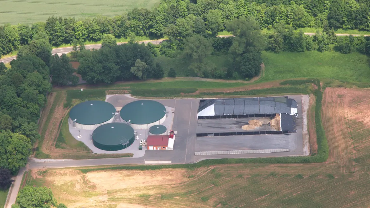

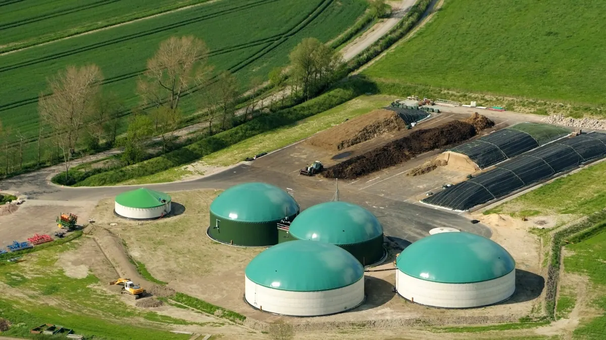
A typical agricultural biogas plant consists of several lines: substrate reception and feeding, digesters (with mixing and heating), biogas storage, a gas cleaning system, a cogeneration unit (CHP), and tanks and infrastructure for managing the digestate. They are complemented by automation, safety systems and energy infrastructure. Below we go through the elements in the order of the flow of material.
1. Substrate yard and storage
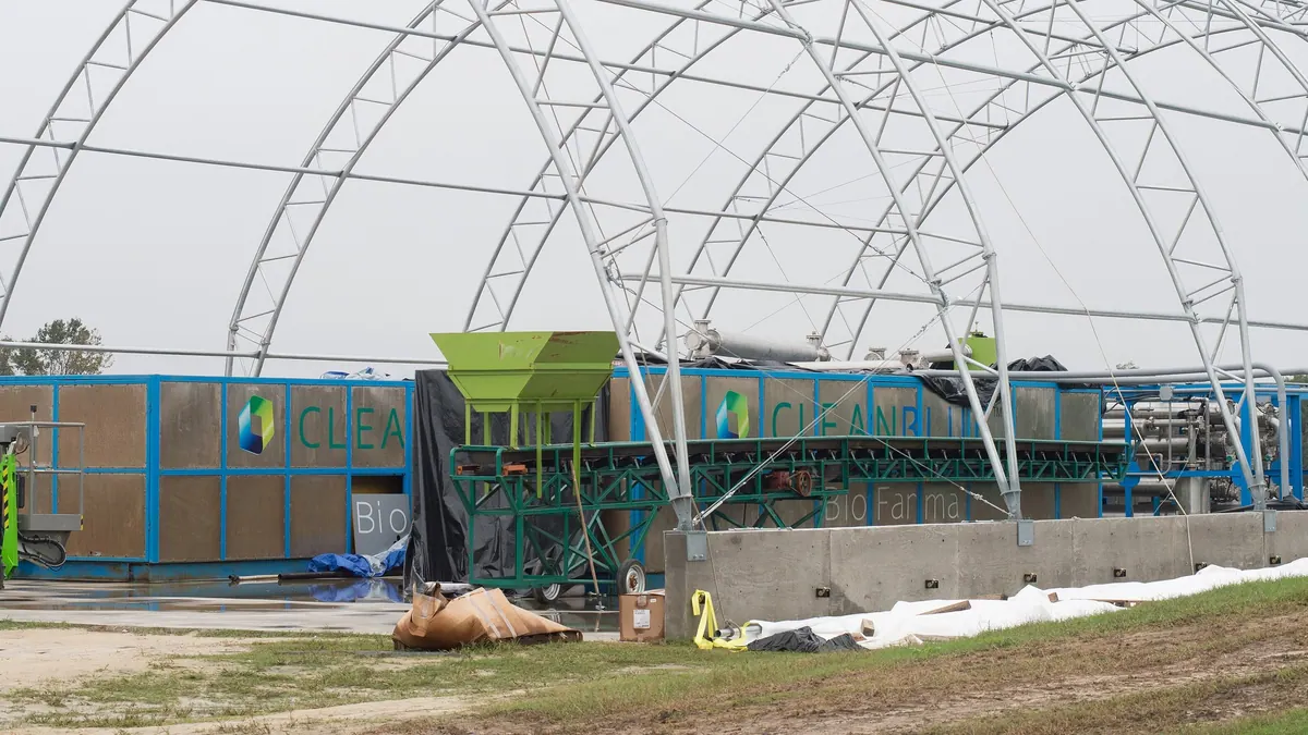
Silage pads with leachate collected in a tank, silos or clamps for silages, slurry tanks, a manure store. The dimensions follow from the annual substrate requirement and losses. Hard surfacing and drainage reduce contamination with sand.
2. Feeding
A solid substrate feeder (a trough with an auger, or a piston type), pumps for slurry and liquid substrates, and optionally shredders and foreign-body separators. A weighing system or mass recording makes a balance possible.
3. Digesters
Reinforced concrete or steel tanks, usually cylindrical, with insulation and heating (coils in the walls or external heat exchangers). Agitators ensure homogeneity. A single-stage or two-stage arrangement is most common; the second stage (the post-digester) increases retention time and use of the potential.
4. Biogas storage
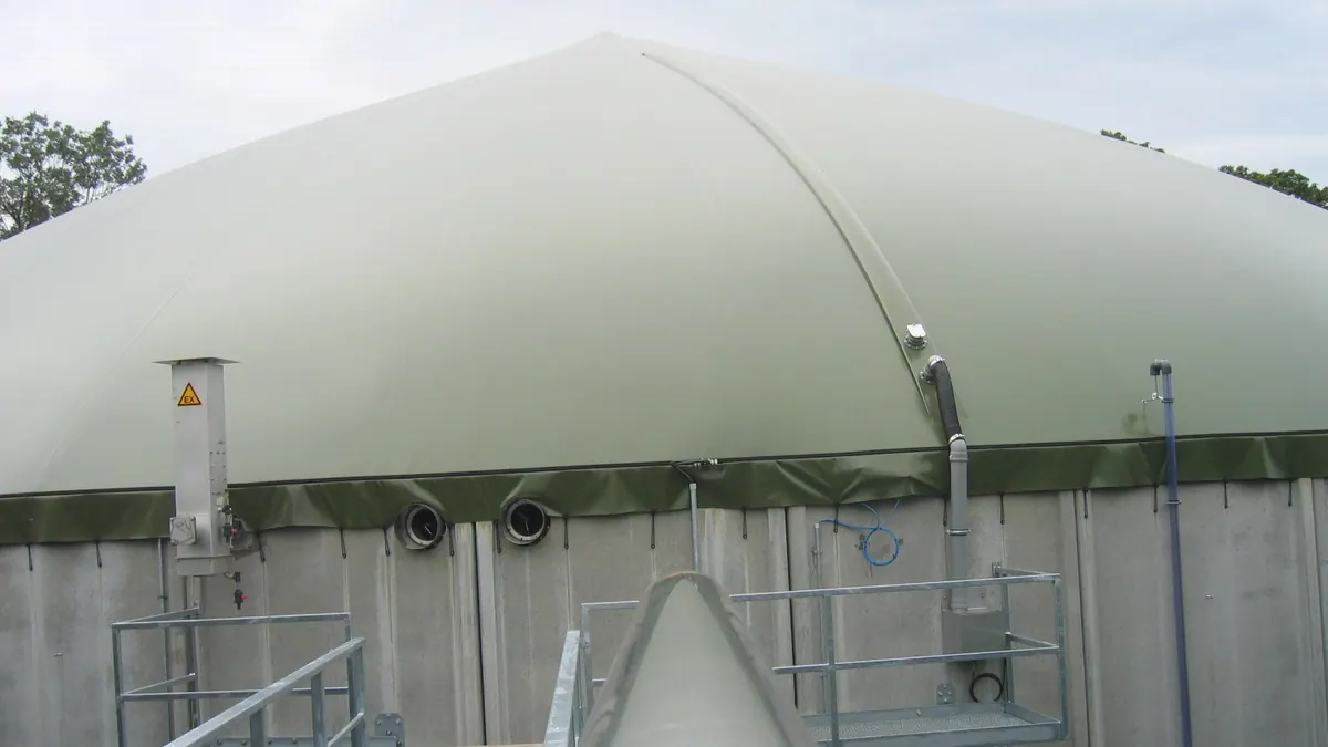
A flexible membrane roof above the digester (often a double membrane) or a separate gas tank. The storage evens out the difference between production and consumption. Details are in a separate article on roofs.
5. Biogas cleaning
Desulphurisation (biological in the digester, supplemented by chemical or activated carbon), drying (cooling, condensate), removal of contaminants (e.g. siloxanes with municipal waste). The parameters are chosen to meet the engine manufacturer's requirements.
6. Cogeneration (CHP)
A gas engine with a generator produces electricity and heat. The heat warms the digesters and can supply dryers, buildings and a district heating network. The electrical efficiency of typical units is in the range of about 36–44%, depending on size and model.
7. Flare and safeguards
The flare burns surplus gas when the CHP is not running; over- and under-pressure valves protect the membranes; gas sensors, detectors and shut-off systems improve safety.
8. Digestate
A digestate tank (closed or covered), a separator (optional), a pumping system and tanker loading. The storage capacity is chosen for the periods when fertilisation is restricted by regulations.
9. Automation and monitoring
A PLC controller, SCADA, parameter logging, remote access, alarms. It is described in a separate article.
10. Energy infrastructure
A grid connection, a transformer station, switchgear, synchronisation systems, metering.
Design dependencies
| Parameter | Follows from |
|---|---|
| Digester volume | daily feed × HRT, OLR |
| CHP capacity | methane production × efficiency |
| Gas storage capacity | CHP operating profile, failures |
| Digestate tank | number of days of storage (periods without application) |
| Silage pad area | annual quantity of silage and clamp height |
| Heat for heating | digester temperature, insulation, climate |
Scaling example
Assumptions: a plant with 500 kW of electrical capacity, electrical efficiency 40%, calorific value of methane 9.97 kWh/m³, operation 8,000 h/year. Chemical power of the fuel: 500/0.4 = 1,250 kW, or about 125 m³ CH₄/h (1,250/9.97), about 3,000 m³ CH₄/d. At a yield of 0.30 m³ CH₄/kg VS, about 10,000 kg VS per day is needed. With such a feed and an OLR of 3 kg VS/(m³·d), the digester volume is about 3,300 m³. This is a simplified sketch, and the designer will take account of seasonality, reserves and local conditions.
Stages of implementation
- Concept and substrate balance (contracts, crop plans).
- Location, connection conditions, environmental decisions and permits.
- Process and construction design.
- Construction, leak tests, commissioning.
- Operation, servicing, optimisation.
The scope of the required permits depends on capacity and location; it should be established with the designer and the authorities.
The most common investment mistakes
- too small a substrate reserve and no long-term contracts,
- underestimating digestate storage,
- no plan for using the heat,
- too small a gas storage,
- economics built solely on an optimistic yield from the literature.
Order of design decisions
It starts with the substrates (type, quantity, availability, price and contracts), then comes an assessment of the options for managing the digestate (area of fields, storage, recipients), then the choice of scale and process solution, and finally the selection of equipment. Reversing this order — buying the unit before securing the substrates — is one of the most common causes of economic trouble.
Documentation and acceptance
Before commissioning, the as-built documentation, leak-test records, material certificates, explosion-hazard zone documentation, operating instructions and an emergency plan should be compiled. Good practice is acceptance with the participation of an independent expert and a written list of defects with deadlines for rectification, before the plant is accepted for operation.
Sources
Related articles