
BiomethaneGuide
Biomethane grid injection station: components, layout and functions
The injection station is the last element of a biomethane plant: it measures the quality and quantity of the gas, regulates pressure, odorises and cuts off non-compliant gas. We describe the components and the order of the equipment.
Other language versions: polski.
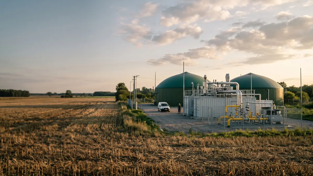
A biomethane injection station is a set of equipment between the upgrading installation and the operator's gas pipeline. It has four tasks: to measure the quality and quantity of the gas, to bring its pressure to the value prevailing in the grid, to give it a smell (odorise it) and to guarantee that gas which does not comply with the requirements does not enter the grid. Although physically it is often a container or a gas station building, functionally it is an element for which both the producer and the operator are responsible.
Typical layout
- Receiving gas from the upgrading installation – an inlet with a shut-off valve and filters.
- Quality measurement – a gas chromatograph, water dew point measurement and, where needed, oxygen, H₂S or hydrogen analysers. The data are used for settlement (calorific value) and for controlling the shut-off valve.
- Conditioning – optional enrichment with propane (LPG) to reach the required calorific value or Wobbe index, and dosing of the odorant.
- Compression – if the outlet pressure from the upgrading is lower than in the grid, a compressor is needed (usually reciprocating or screw). The pressure range depends on the local grid, e.g. medium or elevated medium pressure.
- Regulation and safeguards – a pressure regulator, safety valves, quick-closing valves, overpressure protection systems.
- Custody-transfer metering – a gas meter (e.g. ultrasonic, turbine, rotary) with a volume corrector, which converts the volume to normal conditions and, with the calorific value, to energy.
- Cut-off and gas return – a three-way valve directs gas that does not comply with the requirements back to the upgrading or to the flare.
- Telemetry and control – data transmission to the operator and the dispatch centre.
Division of responsibility
In a typical concept the biomethane producer owns the installation up to the connection point, and the operator owns everything from the connection point onwards (the pipeline, the connection, often its own metering systems and a metering station). The exact division depends on the connection conditions and the agreement; in Poland the producer is responsible for the quality of the injected gas, and the operator has the right to refuse to accept gas that does not meet the parameters. The details should be agreed with the relevant grid operator, e.g. Polska Spółka Gazownictwa or the transmission operator GAZ-SYSTEM in the case of a high-pressure grid.
Grid pressure and absorption capacity
A distribution grid has limited absorption capacity: if gas offtake on a given section falls (e.g. in summer), the biomethane may have nowhere to flow. The solution can be a connection to a higher-pressure grid, reverse compression or buffer storage (e.g. grid extension). Analysis of summer flows is one of the key elements of the connection analysis. The pressure at the injection point itself must be higher than in the grid, so the design of the compression system depends on the highest possible pressure in the grid.
Example: sizing a compressor
Assumptions: biomethane 400 m³/h (normal conditions), upgrading outlet pressure 1.2 bar(a), grid pressure 8 bar(a). The compression ratio is ≈ 6.7, so a multistage compressor is needed. The theoretical power of isothermal compression for an ideal gas: W = p₁V₁·ln(p₂/p₁); for a flow of 400 m³/h (p₁V₁ = p₀V₀ at p₀ ≈ 1.013 bar) and ln(8/1.2) ≈ 1.90 this gives about 21 kW; after allowing for efficiency and imperfect cooling the real power is usually 1.5–2 times higher, i.e. several dozen kW. The designer makes the exact calculations; what matters is that compression from about 1.2 bar(a) to 8 bar(a) is a separate, significant consumer of energy.
Safeguards
- Automatic closing of the valve when quality limits are exceeded (O₂, H₂S, dew point).
- Protection against gas flowing back from the grid into the installation (non-return valve).
- Gas detection in the enclosure and ventilation; explosion hazard zones in accordance with the ATEX Directive.
- Emergency shutdown (ESD) and signalling in the control room.
Typical problems
- Pressure mismatch – start-up without agreement with the operator.
- Chromatograph calibrations that are too infrequent.
- No emergency flare, so gas that does not meet the requirements is released to the atmosphere.
- Underestimated grid absorption capacity in summer.
Order of preparatory work
The design of the station should be developed in parallel with the design of the upgrading installation, because the outlet pressure, flow and gas composition determine the selection of the compressor, gas meter and valves. It is advisable to obtain from the operator in advance data on the operating and maximum pressure at the connection point, the minimum summer gas offtake on the section, and the requirements for communication and telemetry protocols. A lack of these data at the outset leads to design changes during construction, which is one of the more common causes of delays in commissioning biomethane plants.
Summary
The injection station combines measurement technology, regulation and safeguards. Well designed, it minimises the risk of injection being suspended and of settlement disputes, and when agreed with the operator already at the stage of the connection conditions it saves costly corrections.
Sources
Related articles