
BioLNG and bioCNGGuide
Gas requirements for liquefaction: CO₂, water, H₂S, mercury and nitrogen upstream of a micro-liquefier
A liquefier requires far purer gas than the grid: CO₂ of the order of several dozen ppm, water below 1 ppm, trace H₂S and mercury. We describe the limits, the reasons and the methods of final purification.
Other language versions: polski.
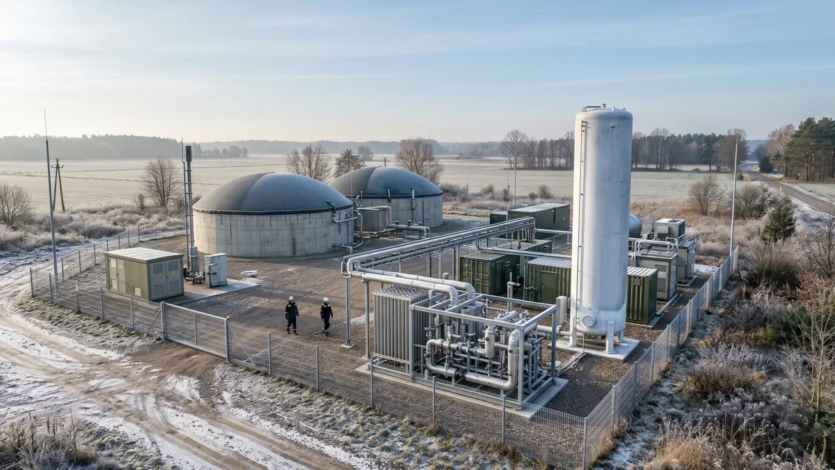
Gas directed to a micro-liquefier must be much purer than biomethane injected into the grid, because at a temperature of about −162°C impurities that are harmless in the grid freeze and clog the exchangers. Typical orders of magnitude required by suppliers are: CO₂ below several dozen ppm (often 50 ppmv), water below 1 ppmv, H₂S at a level of a few ppm, mercury practically absent and limited heavy hydrocarbons. The detailed limits follow from the design of the liquefier and must be confirmed in the supplier's specification.
Why these limits
In a liquefier the gas flows through exchangers with narrow channels. When the gas composition exceeds the solubility of impurities at low temperature, the impurities turn solid and deposit on the walls, which lowers efficiency, increases the pressure drop and forces downtime. Mercury destroys aluminium exchangers by forming amalgams and corrosion. Oxygen in liquid methane is also undesirable for safety reasons.
| Impurity | Typical inlet limit (order of magnitude) | Hazard |
|---|---|---|
| CO₂ | below about 50 ppmv | freezing (dry ice) |
| Water | below about 1 ppmv | ice, hydrates, clogging |
| H₂S | a few ppmv | corrosion, LNG quality requirements |
| Mercury | trace (µg/m³) | aluminium corrosion |
| Benzene and heavy hydrocarbons | up to about a few ppmv | freezing |
| Siloxanes, VOC | very low | contamination, deposits |
| Oxygen | low | safety |
| Nitrogen | limited (depending on the application) | LNG composition and parameters |
The values are indicative: each manufacturer gives its own specifications, and the quality of LNG for vehicles is defined by additional standards.
How to meet the requirements
- Upgrading with low CO₂ content. For most separation technologies the CO₂ content of biomethane after single-stage separation is from several dozen to several thousand ppm, so an additional CO₂ removal stage is necessary.
- Adsorption on molecular sieves (TSA). Zeolite beds in a temperature swing cycle remove CO₂ and water to a level below the limit. Regeneration requires hot gas.
- Activated carbon for removing H₂S, VOC, siloxanes and mercury (often impregnated).
- Cryogenic CO₂ separation in a system integrated with the liquefier.
- Monitoring – analysers of trace concentrations of CO₂ and water at the liquefier inlet with an alarm.
Nitrogen
Nitrogen in the inlet gas is usually not removed in micro-liquefiers; it remains in the product or goes into the boil-off gas. Because it affects the LNG parameters, its content is limited at source: hence biological desulphurisation with air dosing may be inadvisable in the case of bioLNG (see the article on pretreatment).
Example: CO₂ control
Assumptions: gas after membrane upgrading contains 2.0% CO₂ (20,000 ppm). The liquefier requires ≤ 50 ppm. The molecular sieve must therefore reduce the concentration 400-fold. At a flow of 400 m³/h the CO₂ to be retained: 400 × 0.02 = 8 m³/h ≈ 15.8 kg/h (1.98 kg/m³). With a sorbent capacity of, say, 5% of mass (an assumption), about 380 kg of CO₂ is consumed per day → about 7.6 t of sorbent to be regenerated per cycle; in practice several beds must operate alternately. This shows that the first solution is to improve upgrading (e.g. amines or cryogenics) instead of large TSA beds.
Good practices
- Agree the liquefier's inlet specification with the upgrading supplier so that both systems are selected together.
- Install double measurement of moisture and CO₂ upstream of the liquefier.
- Plan regeneration and replacement of beds in the service schedule.
- Provide a gas buffer so that short disturbances in quality do not force a shutdown.
- Keep a register of quality measurements, because it makes diagnosing problems easier.
Where to check specifications
Inlet specifications are part of the technical documentation of the liquefier offer, and the quality of LNG as a vehicle fuel – of standards and customers' requirements. Before deciding on a supplier, ask for a table of limits for all components, together with the measurement method and the permissible variation over time (short-term exceedances, average values). The answers to these questions make it possible to assess whether the final purification system will be too modest or too extensive relative to actual needs.
Consequences for the design of the whole biomethane plant
The liquefier's requirements affect the choice of upgrading technology, the compression system and the method of desulphurisation. If bioLNG is planned, it is sometimes advantageous to design a cryogenic train from the outset in which CO₂ separation and liquefaction are integrated, rather than attaching a liquefier to a finished grid installation. Such integration shortens the gas path, reduces the number of devices and limits methane losses, but makes the project dependent on a single system supplier. The calculation is therefore worth performing for both variants, including the cost of conversions if the decision to liquefy is taken only after the installation has been commissioned.
Summary
For a liquefier ppm count, not per cent. Make sure that the final purification system is designed with a margin and that its cost is included in the bioLNG calculation.
Sources
Related articles