
BiogasAnalysis
Condensate in the biogas pipeline: where it comes from, what damage it causes and how to prevent it
Biogas from the digester is saturated with water vapour, so water condenses in a cooler pipe. The scale of the phenomenon, the consequences for fittings and the engine, and principles for designing drains.
Other language versions: Polski, Deutsch, Español, Français, Italiano, Nederlands.
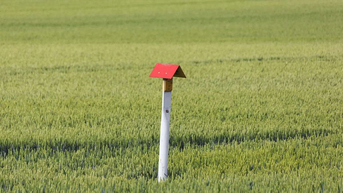
Condensate in a biogas pipeline forms because the gas leaving the digester is saturated with water vapour at process temperature, while the pipeline and surroundings are cooler: cooled gas cannot hold the same amount of vapour and part of the water condenses. The condensed water collects at low points, contains dissolved acidic components and leads to corrosion, blockages, freezing and disturbances to measurements and engine operation. That is why condensate removal and gas drying are part of the design, not an add-on.
The scale of the phenomenon
Saturated gas at the temperature of a mesophilic digester (approx. 38 °C) contains about 45 g of water vapour per 1 m³ of gas (this remains an indicative value, because it depends on pressure and the exact temperature). At 10 °C saturated gas can hold only about 9 g/m³. The difference, about 35 g for every 1 m³ of gas, condenses in the pipe. At a flow of 1000 m³/h this amounts to the order of several dozen kilograms of water per hour, i.e. about a tonne per day. This shows that condensate is not a minor phenomenon, and that in winter, with a larger temperature difference, there is more of it. Details of gas drying are in the article Biogas drying: condensation, cooling and adsorption.
What condensate contains
Condensate is not pure water. Dissolved in it are CO₂ (which forms carbonic acid), H₂S (a weak acid, but aggressive towards steel), ammonia and trace amounts of organic compounds, as well as particles of foam or impurities. For this reason it is corrosive to carbon steel and to some fittings, and its discharge requires care.
Consequences
| Consequence | Mechanism |
|---|---|
| Corrosion | Acidic condensate at low points and on the bottom of the pipe |
| Water blockages | Water in a pipeline "sag" reduces the cross-section or blocks flow |
| Freezing | Ice in drains and lines at low temperatures |
| Measurement errors | Water in gas meters, flow meters and analysers |
| Damage to the blower and engine | Water entering the blower or the engine's gas system |
| Disruption of safety devices | Frozen or flooded drains and valves |
| Transport of contaminants | Carry-over of siloxanes or particles to downstream equipment |
Prevention at the design stage
- Gradients. Pipelines are routed so that condensate flows to the drain points; "sags" and horizontal sections are avoided.
- Drains at the lowest points. Hydraulic traps, condensate pits or drain valves; with hydraulic traps, the height of the liquid column must take into account the maximum gas pressure.
- Insulation or burying. Pipes outdoors are insulated or laid below the frost depth, which reduces condensation and the risk of freezing; see Will a heating cable protect the system from frost.
- Gas drying. A gas cooler (condensation at a controlled place) upstream of the blower and engine or upstream of upgrading; a well-designed one limits condensate further along the system.
- Materials. Stainless steel, PE or other plastics suitable for biogas, in line with the design and standards; carbon steel in contact with condensate requires protection.
- Redundancy and access. Drains accessible for inspection, with the possibility of isolation and safe emptying.
Operation
- Regular checks of drains: free flow, liquid level in the traps, no freezing.
- Topping up the liquid in hydraulic traps so as to prevent gas escaping.
- Checking pipes after the spring thaw and after heavy rainfall (a change in the ground can change the gradients).
- Monitoring the points from which a large amount of condensate regularly drains: a change in quantity may indicate a fault in the drying.
- Records and inspections in the operating log.
Safety
Condensate pits and drains are places where gas, including H₂S, can accumulate. Ex zoning rules apply (see ATEX at a biogas plant), as do procedures for work in confined spaces (see Work in confined spaces). Activities such as emptying, replacing a trap or entering a pit are carried out by trained persons in line with the plant manual and risk assessment. Condensate is discharged in the manner provided for in the design and permits; it is not poured onto the ground.
Summary
Condensate is a natural consequence of the gas being saturated with vapour, so it cannot be avoided, only designed for so that it condenses at a controlled place and is safely discharged. The values depend on temperature, pressure and the pipeline route; they require calculations for the specific plant. See also Heat balance of a biogas plant in winter.
Example checklist for a drain inspection
- Do all low points on the route have drains, and does their position match the diagram?
- Are the traps filled with liquid, and does the column height correspond to the operating pressure?
- Are the drains protected against freezing in winter, and is the protection working?
- Is access to the drains safe and marked, and is the emptying procedure known to the operators?
- Is the quantity of condensate collected recorded and compared with earlier periods?
- Does gas drying upstream of the blower and engine work as intended?
Sources
Questions and answers
Can biogas condensate be poured into the sewer or a tank?
Not without assessment. Condensate contains dissolved gases (including H₂S) and corrosive substances, and how it may be managed depends on permits and the facility's procedures. It is usually returned to the process system in the way provided for in the design.